As you read this article you’re first impression will be that this is a nightmare (and it is). I want to say, normally this process is a pain in the butt, but goes smoothly. Its tedious work and in almost every case, the studs can be removed without going to the extreme that was required in my case. I received help and advice from several mechanics and machinist who have a lot of experience with broken stud removal. Every one of them said they have never seen one this difficult. Yah, thanks, that encouraging 🙁
Ford has always had an issue with broken studs on their modular engines,the V6, V8, and the V10. The V10 is used in a variety of Ford fleet vehicles, pickups, vans, and of course, the F53 motor home chassis.
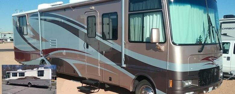
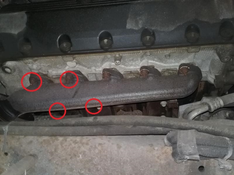
When we bought our 1999 Southwind last year, during my pre-purchase inspection, I could see two studs broken on cylinder #9. The nuts were broken off even with the manifold and I could see the stud.. What I couldn’t see, I had five more studs broke, the nuts were rusted to the manifolds on the top and bottom of cylinder #4 and #5, and the top only on cylinder #10. These were broke below the surface of the head, and the broken piece and the nut were stuck to the manifold, held in place by a small build up of rust. We drove the Southwind over a year and 7,000 miles like this. I could hear exhaust leak especially when first starting and the engine was cold, a steady “tick tick tick”, but it wasn’t to bad. This spring, I didn’t want to press my luck any more, so I decided it was time to get this fixed.
I’ve worked on broken studs before, so I knew what I was getting into. Basically, try several methods. the studs will come out, but its a tedious job. I did a lot of reading on the Ford Truck Enthusiast forums and seen this was a common problem on Fords V10’s. Fortunately, the F53 chassis has a lot more room to work in than the folks with pickup trucks or vans. In my case, the studs didn’t appear to be broken inside the head, but are broken at the nut. Hopefully this would go smoothly. WRONG, I had two studs that were broken above the head, I had 5 that were broken below the head. I would break 5 more while attempting to remove the studs from the heads.
CONSIDERATIONS
A couple considerations / questions I had before I started to tackle this job:
- Should I replace the manifolds with headers
- How best to remove the old studs: cut, torch, turn out with wrench.
- Should I repair or replace the EGR tube or eliminate the EGR tube and sensors.
HEADERS
My V10 is an early model V10 and is known as the “non-pi” (non performance improved) engine. Its a 275 hp version of the V10. The exhaust manifolds are square and restrictive compared to newer model that are round and improved flow, the manifolds are not interchangeable. I decided to replace the manifolds with headers. Although I didn’t see any broken studs on the passenger side (they were broken, I just couldn’t see them), I needed to remove both exhaust manifolds to do the headers.. When I removed the passenger side manifold, I discovered I had 4 more broken studs.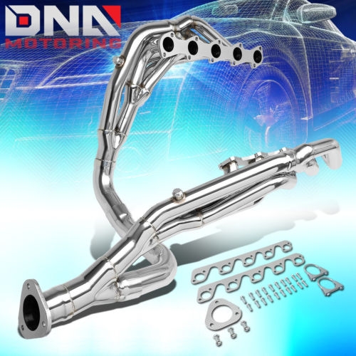
I didn’t want to spend $1,400 – $1,800 on Banks headers, so I ordered a set of DNA Long Tube headers ($270) that fit on 1999 F250 and F350 pickups. After they arrived I was happy to report that they fit my F53 just fine with no interference issues, but they would require some modifications to where the connect to the rest of the exhaust system, and also heat shields to protect other components.
REMOVING THE MANIFOLDS
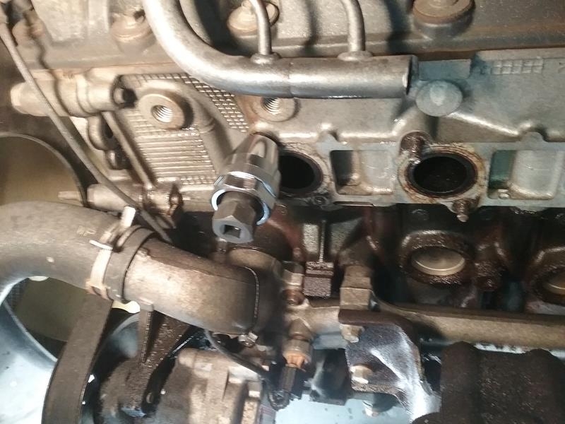
As I was removing the manifolds, when I touched the nuts on Cylinder 4, 5, and 10, the nuts and broken part of the stud fell off.. This is when I discovered I had a lot of broken studs and didn’t know it. After getting the manifolds off I had to remove the existing studs. 6 of the good studs came out, 7 of the good studs broke off even with the manifolds. I now had 12 broken studs that needed to come out..
The nuts on the bolts that secure the “Y” pipes to the manifold were rusted very bad and none of my sockets would move them. I used a die grinder to cut the bolts.
The 3 bolt flange bolts that connects the Y pipe to the exhaust pipe came off easily. I left the O2 sensors on the Y pipe and disconnected the electrical plugs. The Y pipe came out very easily.
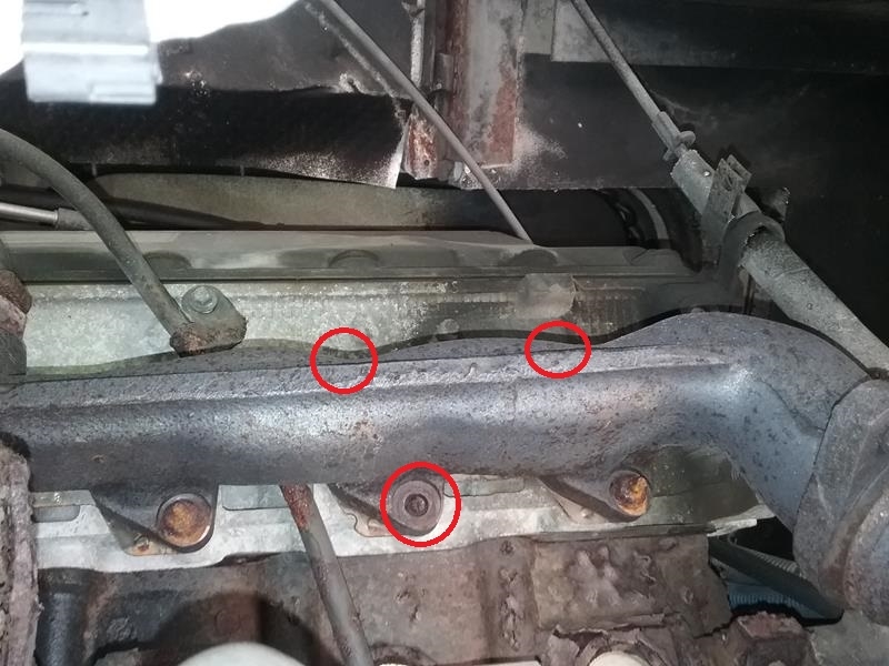
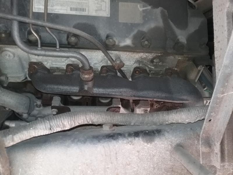 My V10 has a EGR tube on the drivers side manifold. I attempted to remove the fitting from the manifold but it wasn’t going to budge (rusted on). I used the die grinder to cut the tube in one of its straight areas in case I decide to re-use the manifolds and EGR, I could use a pipe coupler to re-connect the EGR tube pieced together.
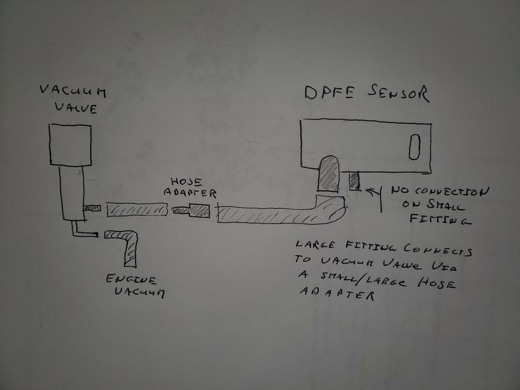
On the headers, I won’t be reconnecting the EGR, I made a plate to block off the EGR port on the intake manifold. I’ll either build a EGR simulator circuit to trick the electronics into thinking the EGR system is installed and functional, or spoof the sensor by re-plumbing the vacuum lines to the sensor. The re-plumbing worked OK so thats what I currently have.
Spoof EGR/DPFE sensor – I re-plumbed the vacuum lines to trick the DPFE sensor into thinking it was seeing differential pressure from the EGR tube. Remove the vacuum line from the control valve to the EGR valve, Using an adapter, run this line fr to the large fitting on the DPFE sensor. Remove the line from the small fitting on the DPFE sensor. It will now be open to atmosphere. (no connections)
REMOVING BROKEN STUD METHODs
To anyone who’s ever done this, when you mention removing broken exhaust studs, this sends a chill up their spine. Although I knew this wasn’t going to be a pleasant experience, I’ve done it before and knew what to do, and, I knew when I was getting in over my head and it was time to call in the professionals..
Methods of removal I tried
- Soak in PB blaster, the longer the better, a few weeks, spray it a couple times a day.
- Heat the surrounding area.
- If broken stud exposed, try vise grips, rock back and forth.
- if exposed, use an extractor tool.
- If broke below surface, weld a nut to the broken stud.
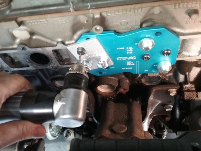
- Use drill guide template, drill center of stud and an EZ out
- Drill slightly small than stud, pick or EZ out, re thread
- drill out entire stud and threads, insert coil repair
- drill out oversize, weld refill aluminum, then re-drill new hole and tap. (requires head removal)
REMOVING MANIFOLDS / BROKEN STUDS
When removing the manifolds, 6 of the studs came out, 7 of the studs broke off at the nuts, even with the manifolds. 5 studs were already broke and these fell off when I touched them with the socket. 2 were already broke and the nuts were missing.
The stud removal processes did not go well. I was able to get one of the broken studs out with the extractor, but when I was working it, it required a LOT of force on the wrench, and I knew the bolt (stud) was going to break. I got one stud out, and it was very hard, I broke 4 studs below the head surface.
I then attempted the welded nut method. I repeated this 7-8 times, welding nuts on the broken studs, let them cool, attempt to wiggle. no good..
Normally, the above two methods work. Its tedious, but they do come out. HOWEVER, In this case, they didn’t
I then attempted to use the drill method. The drilling went smoothly using a guide template to line up the hole. Cobalt drills made nice holes, I was careful to not drill to far and go into the cooling jacket. The EZ out extractors did not work. I drilled a little larger, still no good, I finally drilled and used a tap, this worked but I buggered up the hole. I tried this one more time on another stud. After that, I decided to pull the heads..
PULLING THE HEADS
My only regret, I wasted a lot of time attempting to remove studs, After failure with the extractor tool and the welded nut method, I should have made the decision to pull the heads.
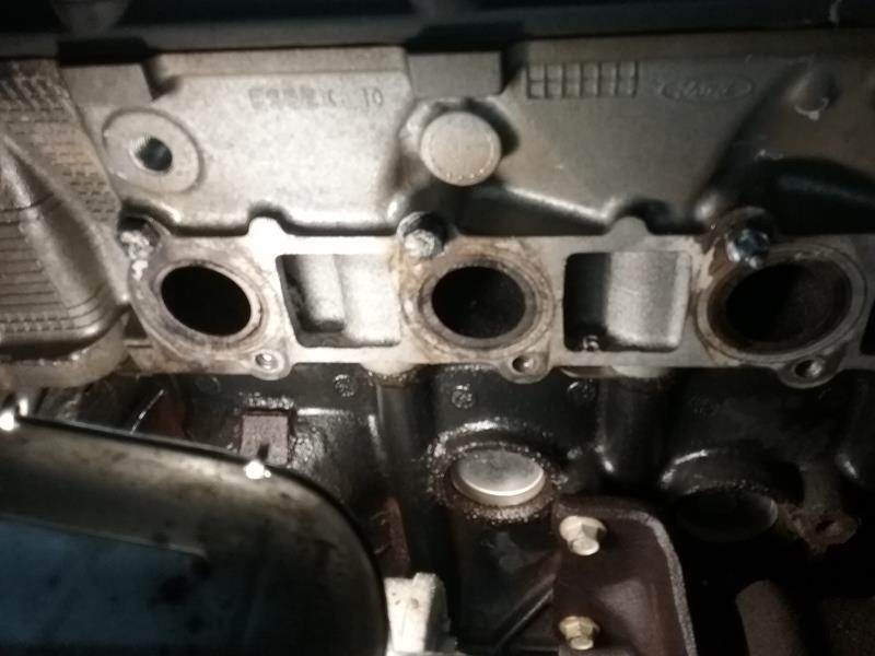
For me. pulling heads was a good thing.. One of my concerns about buying a 18 year old vehicle that spends the majority of its time parked. whats the condition of the inside of the engine.. Pulling the heads allowed me a closer inspection of the innards.
NOTE – Oil burning. We put about 7500 miles on the V10 since we bought it. I noted is was burning about 1 qt of oil every 1200-1500 miles. I wanted to see if there was anything in the engine that could resolve this.
Getting stuff ready
Service CD from Rock Auto. I printed and bound the 200 pages that referred to the engine.
Photos – Take a lot of photos at every step. electrical connectors, hoses, tubes, etc.
Plastic sandwich baggies. Keep bolts, nuts etc in bags. attach the bags to the item that was removed
Paper towels, hand cleaner, mats and large pieces of cardboard to walk / crawl on.
The only special tools I needed was a puller for the harmonic balance pulley, the fan clutch wrench, and the sleeve things to remove fuel line connectors
Taking it apart
Take a lot of photos, from a lot of angles. especially before removing stuff, or if you run into something unusual.
After I removed the spark plugs, I did a compression test. Later when I re-assembled, I repeated the test to verify I had timing correct.
This is basic, start removing stuff from the top and work your way down. I bought a box of zip lock sandwich bags and kept all the bolts, nuts, etc in a bag and tied the bags to the components they belonged to. Believe it or not, after re-assemble, I had no parts left over. 🙂
No need to remove the water pump or alternator, but if you have original water pump, I’d recommend replacing it at this time.
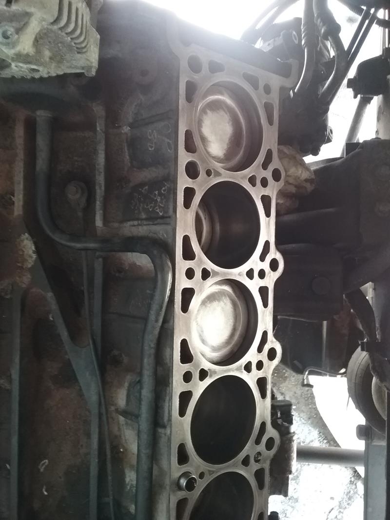 IMPORTANT – Set the crank so the key is at 12 o’clock. This is NOT the timing position, but is a safe position. When at 12 o’clock, none of the pistons are high enough to contact open valves. In the above photo, Cyl 1 and 3 can be seen near the top. Cyl 6 and 7 are in the same position near the top.
- Verify the batteries are disconnected and no shore power. We’ll have a lot of open connectors and fuel lines and don’t want to risk anything shorting out or making any sparks.
- Place mats on the inside to keep from tracking dirt, oil etc inside.
- Raise front end. I used my leveler jacks and then placed stands under the front axle.
- Remove front tires.
- Remove serpentine belt
- Remove crankshaft harmonic balance bolt. I had to use the “bump the starter” trick to get mine lose.
- Using a puller, remove the harmonic balance
- Remove dog house cover.
- Remove EGR plumbing and sensors.
- Remove intake plumbing
- Remove hoses, oil, vacuum, from top
- Remove fuel lines. These are those quick disconnects that you need the special tool for. I put the ends in a plastic bag to keep them clean. NOTE – Remove the gas tank cap. This will prevent the fuel tank from building up pressure and pushing fuel out these disconnected fuel lines.
- Remove transmission and oil dip stick mounts and tube from tranny and engine (wiggle and pull)
- Remove fuel injector and COP connectors
- Remove COPs,
- Use compressed air to blow crap out of spark plug holes. A lot of crap gets down into those cavities. You want all this out before removing the intake manifold.
- Remove intake snorkel that connects the throttle body to the air cleaner..
- Remove thermostat, upper and lower cooling hoses, and overfill tank hose.. You can leave them connected to the oil cooler, or not.
- Remove intake manifold bolts and remove intake.
- Remove the spark plus, I kept mine in order so I could inspect them later
- Remove the temperature sensor from the left head. It may have a brass washer under it.
- Remove fan and clutch, it will lay inside the shroud against radiator, so protect radiator with small piece of cardboard.
- Remove two bolts from top of shroud and slightly raise it to release the bottom clips.
- Remove fan, clutch and shroud out the bottom.
- Unbolt the A/C compressor and power steering pump. No need to disconnect them.
- The PS pump bracket needs to be removed from the engine as its attached to the front cover
- Remove the engine wiring harness
- Remove the radiator. Four bolts on the bottom support and it comes out the bottom.
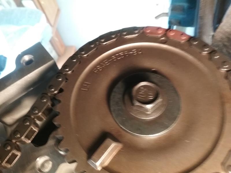
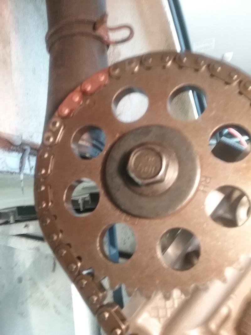
- Remove valve covers. Observe the timing marks on the front of the cam gears.
- Use a breaker bar or whatever and knock the cam sprocket bolts lose. DO NOT REMOVE THEM YET
- Remove the front timing chain cover. There are hidden bolts and variable lengths. make sure to remove the three rubber seal pieces. On re-assembly, You’ll need a chart to show which length bolts go where See photos.
- IMPORTANT – Verify the crank key is at the 12 o’clock, safe position… Do NOT move the crank or cams if the timing chains are disconnected. There is locking tool fixture for this purpose, I don’t have one, so USE CAUTION not to move the crank from the 12 oclock “SAFE” position
- NOTE – On the drivers side head, I needed to remove the balance shaft so I could get a socket on a couple of the head bolts. Remove the balance shaft only.
- Remove all the head bolts, but do not attempt to remove the heads yet.
- Remove the chain guides and tensioners. I kept the left and right sides separated in different bags.
- Slowly remove the crank sprockets, chains, and cam sprockets. It will dribble oil.
- Remove the heads. They will probably dump a small amount of coolant.
- Remove / account for the two guide sleeves on each of the heads. These are the guide sleeves to line up the heads, they may fall out.
- Use paper towels to wipe liquid out of the cylinders
- I removed the cams, rockers, oilers from the heads before taking to shop.
- I took a lot of close photos of the cam so I could see where they came from when I reassembled.
- loosen the cam bolts a little at a time to allow the cam to come up evenly.
REASSEMBLY NOTES
Assemble in the reverse order. Here are some notes of things to watch for.
I put on new head gaskets and exhaust manifold gaskets, but re-used the valve cover, intake, and front cover seal / gaskets. I inspected them carefully and they looked good and resilient.
The temperature sensor on the drivers side head. Verify it has the copper washer under it.
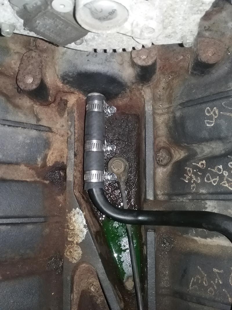 Instead of screwing around with 0-rings on the water pump heater tube. I cut the end of the heater tube off, and then used a short section of heater hose to connect the tube to the nipple. This is a common fix for Ford trucks where the tube has rusted out. They eliminate the tube and just run heater hose all the way.
I installed new COPs ($40 for 10, e-bay) and plugs (Autolite APP-103, check for rebates)
Compress the tensioners and use a nail or something to lock them. The procedure is in the manual.
ASSEMBLY, TIMING – VERY IMPORTANT – Failure to do this will result in bent valves..
Before placing the heads on the block, Verify the crankshaft key is at its SAFE 12 o’clock position, You can see the pistons on cylinder 1, 3, 6,and 7 are all near the top, but far enough down so they will not hit any open valves. The crankshaft must stay in this position until after the heads are installed and ready to install the chains.
Verify the 4 head guide pin sleeves are installed on the block.
Squirt a little oil in each cylinder to wet the sides of the cylinders
Install the heads and torque. I had the cams, lifters, rockers already installed on the heads and torqued. The chain sprockets should be installed, but the sprocket bolts may not be torqued yet. (I torqued the two cam sprocket bolts after I installed the chains, guides, and tensioners.
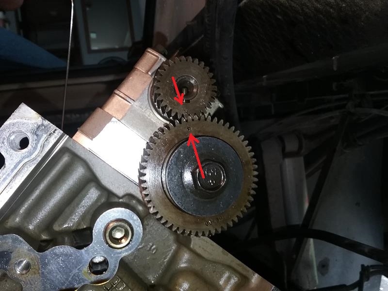
Temporarily remove the drivers side cam sprocket and install the balance shaft on the drivers side head. Line up the dots on the balance shaft gears. Note – Its safe to rotate the cam as long as the crankshaft key is in its safe 12 o’clock position
Position the cam sprockets at their correct timing position. Looking from the front of the engine, the drivers side timing mark (small dot) will be at approximately 12 o’clock position referenced from the cam sprocket bolt. The passenger side timing mark (small dot) will be at approximately the 11 o’clock position referenced from the cam sprocket bolt.
Position the crankshaft key to its timing position. Slowly turn the crankshaft CCW ONLY until the key is now at the 11 o’clock position. If you turn CW or go to far CCW the pistons will hit the valves. Slide a crankshaft chain sprocket on the shaft. The timing dot should be at the 6 o’clock position
 Follow the book procedure on installing the chains, guides, and tensioners. Do NOT move the crank or cams until both sides are finished and the tensioners have been released.
Before proceeding, Slowly rotate the crank by hand to verify no resistance. If its OK, do a quick compression test to verify compression ( I used a old remote starter push-button connected directly to the starter to turn the engine.
CAUTION – Before cranking the engine with the starter, to make sure the crankshaft chain sprockets can’t move or slide off of the crankshaft. I used a short section of plastic pipe as a spacer and snugly installed the crankshaft bolt and large washer to hold the timing sprockets on the shaft.
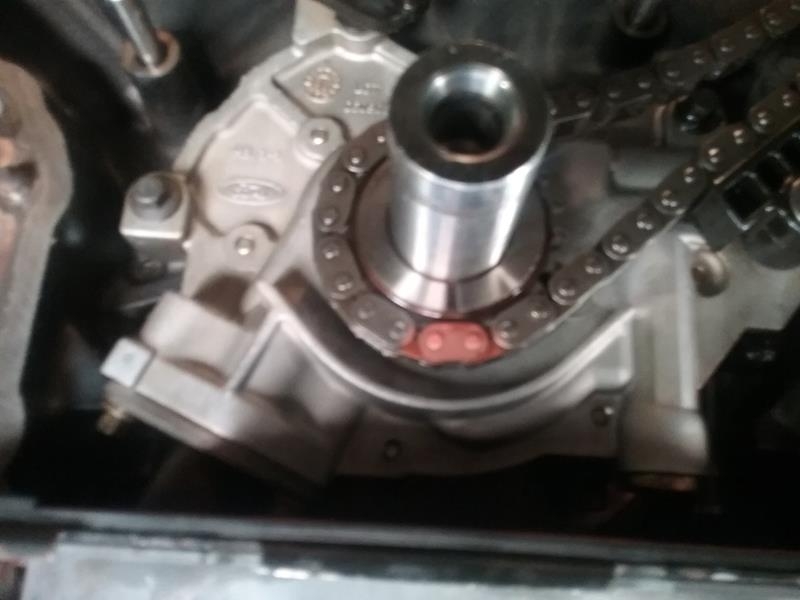
Before installing the front cover over the timing chains, Make sure to install the crankshaft position sensor sprocket. I also installed new crankshaft and camshaft position sensors on the cover.
MACHINE SHOP WORK
I took the heads to my local machine shop, I removed the cams but left the valve in place. The only work needed was the studs, and he said it was OK to leave the valves in. The shop did a good job, but he said it was one of the worst he’s ever see. Out of the 12 studs, he was only able to get three of them out. He drilled three out and was able to install inserts. However, on 6 of them, he had to re-weld aluminum to fill the old stud hole, then re-drill and tap a new stud hole.
There was one minor issue that I didn’t discover until I was putting everything together. On one of the holes that had an insert, evidently he went a little to far and went into the water jacket.. I cleaned the hole and made sure it was dry. I then filled the hole with RTV gasket maker, put RTV on the threads of the stud, then installed a stud in the hole. So far, it seems to be holding.. (NOTE – We have 7500 miles on the engine now, no problems)
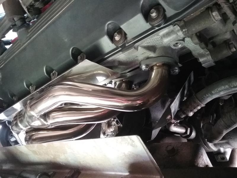
HEADER INSTALL
The headers come with bolts, However to make installing the headers a lot easier, I installed two studs into the heads on both sides. Having a couple studs to “hang” the headers on makes it a LOT easier installing, just make sure you can put a nut on the studs I couldn’t get a torque wrench on the nuts and bolts, but have a good fell for what 20 ft lbs fells like.
Before tightening, I installed the header connector pipe between the left and right sides. I didn’t install the clamps until I ran the engine a couple times allow to allow everything time to reposition itself.
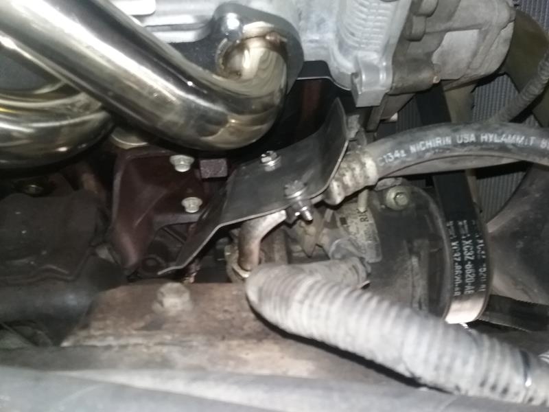
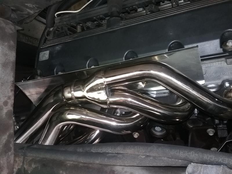
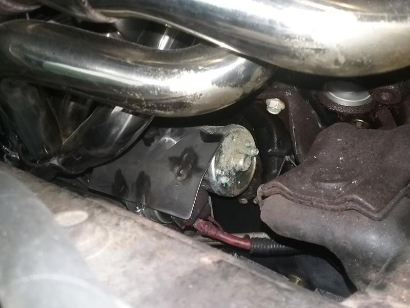
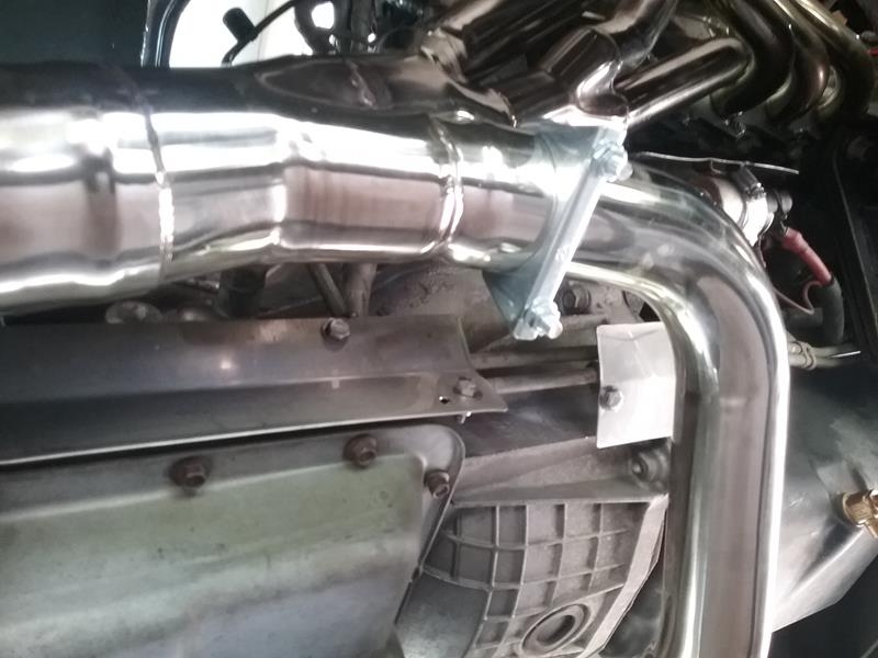
The F250 / F350 headers fit the F53 with no interference problems. I had a couple areas that I was concerned about heat radiation, so I made a couple heat shields to protect these areas; On top, both side near the valve covers. Passenger side front near the A/C compressor, and the starter. I also used some reflective wrap on a couple wire bundles and hydraulic hoses that run on the top of the frame rails, and also the transmission cooling lines on the bottom beside the transmission.
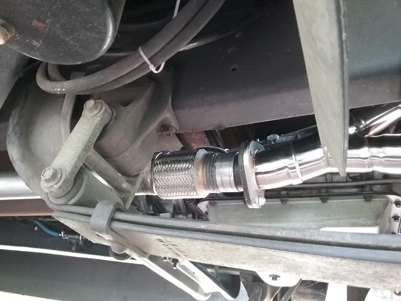
The headers are about 24 inches to short to bolt to the existing exhaust system. I made a new extension pipe that bolts to the headers and then connects to the existing exhaust system. In the new pipe, I added an 8 inch flex pipe. The should eliminate the weight and vibration of the exhaust system being transferred into the headers.
HEADER HEAT SHIELDS
The header tubes are routed differently than the stock manifolds. Things that normally aren’t exposed to heat from the manifolds are now exposed to heat because the tubes are in close proximity.
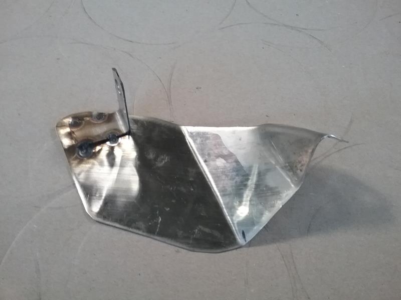
I probably went overboard on heat shields, I have access to thin scrap stainless sheet metal, so was able to cut, bent create heat shields. I first made a template out of cardboard, then transferred this to the stainless for cutting/bending. I used some of the self adhesive type heat shield blanket material around a couple wire bundles that ran across the top of the frame rails. I used the stainless heat shields on the exposed surface of the valve covers, Transmission tubes and side, and the hydraulic hoses and wire bundles on the frame rails, the Oil cooler, and the A/C Compressor.
The thin stainless sheet (24 gauge) pieces can be cut with snips, then bent by hand or brake. I secured the shields with bolts, worm hose clamps, and Adel clamps.
- Valve Covers – the header tubes come up high and radiate on the valve covers.
- A/C compressor – Cylinder #1 tube radiates on the A/C hoses on the back of the compressor.
- Transmission cooler lines beside transmission
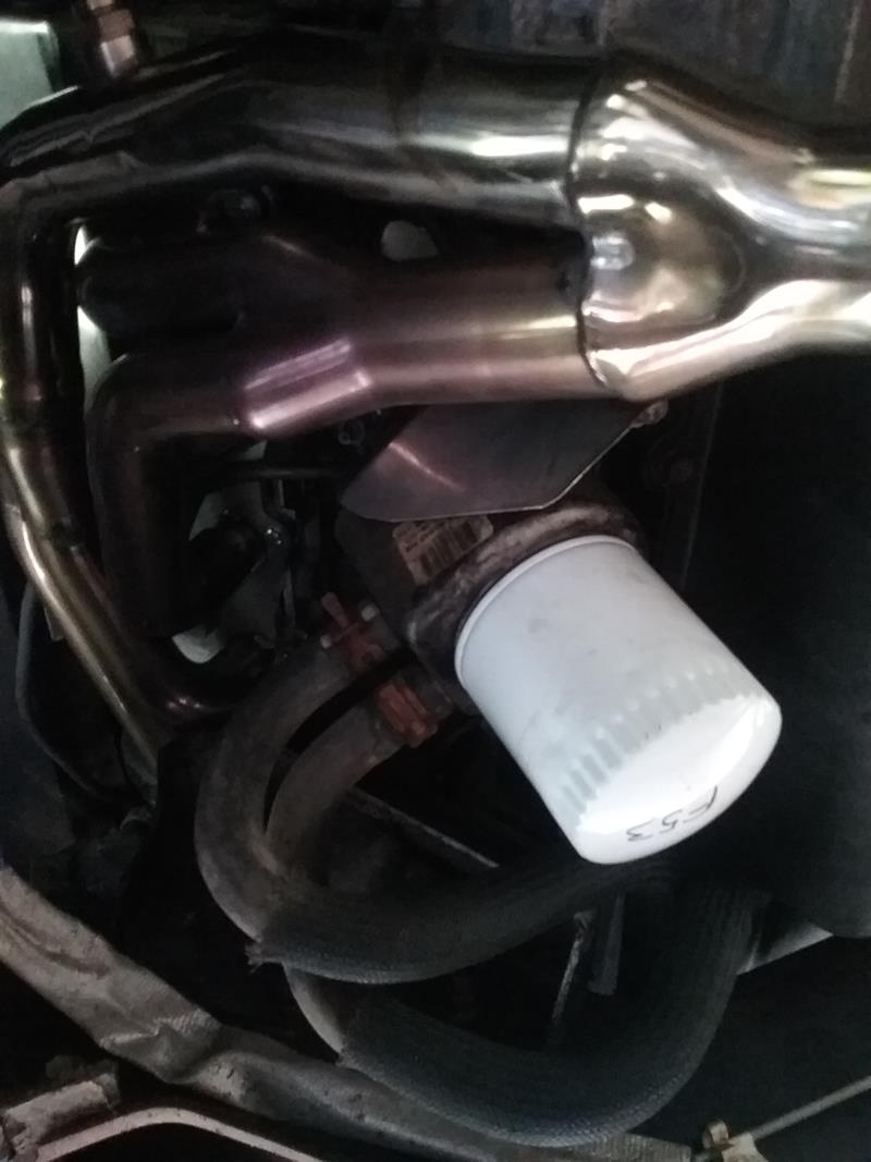
- Oil filter / cooler
- Starter
- wire bundles and hydraulic lines – I wrapped these with the reflector fabric stuff
UPDATE – March 2019
We now have 7500 miles on the new headers. No problems. I checked the header bolts / nuts and found a couple loose. Read HERE for the trip report.
UPDATE – APRIL 2020
No problems. I checked all the header bolts / nuts, everything is still tight.
Man oh MAN! What a great GREAT job! Not only with removing and replacing the exhaust and ALL the EXTRA stuff you did, but documenting all this in this excellent blog is just awesome! It ‘almost’ makes me want to try fixing mine …..if they ever break. But..I said, “ALMOST”! Thanks again, this is fantastic!
Pingback: Upgrade report – A little more power and better fuel economy – 1999 Southwind 35S
So, my annual NY State inspection revealed a broken exhaust manifold stud – top of manifold, #10. This is an ’09 F53 chassis.
Mechanic was replace all studs and make repairs. He found a second broken stud. He was able to get one out but not the other (the on on #10 cyl.) I picked the MH up today – the exhaust is not leaking, as it is. I have no idea about how lonf this stud had been broken. Anyways, I have an idea on a work around for the broken stud. There is a drilled and tapped (unsed) hole 3 or 4″ away from the broken stud and manifold flange. I am going to fabricate a hefty peice of steel plate – 3/8″ – and “clamp” the manifold flange to the head. I hope this makes for a fix on my V-10.
I appreciated your article about this extensive repair you made on the manifold bolt/stud problem. Your chronology and detail create a path for understanding the problem but also the cautions needed for a successful repair. And i thank you for that.
I also have a 1999 Ford V -10 engine in a Four Winds (M.H.) by THOR with the same problem. I have owned it for 21 years and it has 40K miles on it now. I have a question what was the mileage on your motor home when you initially notice the problem and later after you put 7500 more miles on it? Thank you and hope you will reply to my question.
Thank you..
I bought it (I’m the third owner) in March 2017. It had 58,000 miles on it. The damage was present when I performed a pre-purchase
I repaired the exhaust studs in July 2018 with 65,500
The motorhome now has 85,000 miles on it.
Thank you W. I was so astonished to learn this was such a common problem with Ford engines. And it existed for such along time. I now am looking for someone do to the repair. And being a motor home and not a smaller Ford pick up sources are very limited.
Just noticed your story as I was looking for an F53 exhaust diagram. I had a broken EGR tube and couldn’t get the nut out of the manifold so I decided to take off the manifold. Bad idea. I broke 9 out of 10 studs. 2 came out with an extractor, then I tried drilling the rest but most went crooked. Ended up getting the template and making a custom plate and oversize bushings to drill and tap for Helicoils in 4 holes. Wanted to avoid pulling the head at all costs as this happened a week before a planned trip last Sept.
1999 Rexair on F53
How long does each helicoil take to do for you?
I had to take the heads to a machine shop. they had to redrill and reweld several holes